

Over time, drive belt wear is unavoidable. When replacing the belt, routing it incorrectly can reduce performance or even damage the mower. This guide includes a John Deere drive belt diagram for common mower models. Help you replace the belt correctly and get your mower running smoothly again.
What Is a Drive Belt?
Before we look at the diagrams, it’s important to clarify what the drive belt does. On a riding mower or tractor, there are two main belts. The mower deck belt is for spinning the cutting blades. The drive belt, often called the transaxle or transmission belt, is the one we are focusing on here. It transfers power from the engine’s crankshaft to the transmission (or transaxle), which in turn makes the wheels turn. If your blades spin but the mower won’t move forward or backward, the drive belt is the component you need to inspect.
Z Series Zero-Turn Mowers
Zero-turn mowers like those in the Z series use a unique setup with two separate hydrostatic transmissions to provide their signature maneuverability. This requires a specific belt path to power both units from a single engine pulley.
John Deere Z445 & Z665 Drive Belt Diagram
The John Deere drive belt diagram for the Z445 and Z665 models is identical. As seen in the provided image, the belt path is designed for efficiency and constant tension across both transmissions.
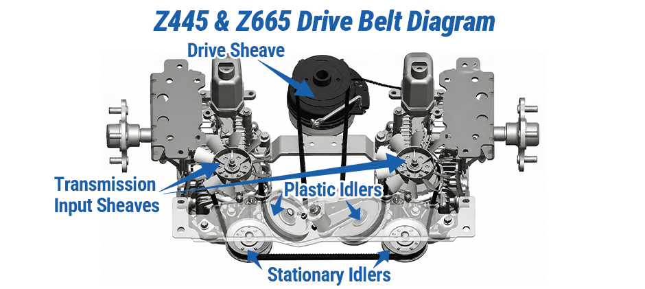
Routing Path: The belt starts at the engine’s electric clutch pulley. From there, it extends rearward, forming a large loop. The belt wraps around the input pulleys for both the left and right hydrostatic transmissions.
On its return path toward the engine, the belt is guided by two stationary idler pulleys. Tension is applied by a spring-loaded idler pulley, which pushes down on the top span of the belt between the two transmissions. This tensioner is crucial for preventing slippage and ensuring consistent power delivery.
D100 Series
The D100 series is a popular line of lawn tractors known for reliability. The drive belt system is more traditional than on a zero-turn, but correct routing around the tensioner is still key.
John Deere D105 & D130 Drive Belt Diagram
The parts diagram for the D105 and D130 shows a system built around a tensioner arm and spring.
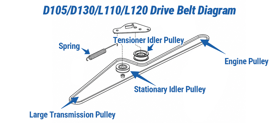
- Key Components: The main components are the large transmission pulley, a stationary idler pulley, and a tensioner idler pulley mounted on a pivoting arm. A long spring attaches to this arm.
- Routing Path: The drive belt creates a loop from the engine pulley to the large transmission pulley at the rear. The belt is routed so that the tensioner idler and stationary idler guide it. The tensioner spring pulls the arm, forcing the idler against the belt to maintain proper tension for the transmission to engage smoothly.
L Series
The L Series, the predecessor to the D Series, features a drive belt system with a very similar design philosophy. The specific layout or part numbers may vary slightly, but the belt tensioning system works nearly the same way as on the D100 models.
Therefore, the diagram provided for the D100 Series can also serve as an excellent visual guide for understanding the system on L Series models like the John Deere L110 & L120 Drive Belt Diagram. Just like in the D Series, the L Series uses a spring-loaded idler pulley that presses against the belt, ensuring there is enough tension between the engine and transmission pulleys for the tractor to move effectively.
X Series
The X Series mowers often feature heavier-duty components, and their drive belt systems reflect this. The tensioner mechanism on models like the X300 and X330 uses a dual-idler setup.
John Deere X300 & X330 Drive Belt Diagram
The drive belt diagram for the X300 and X330 reveals a robust tensioning system.
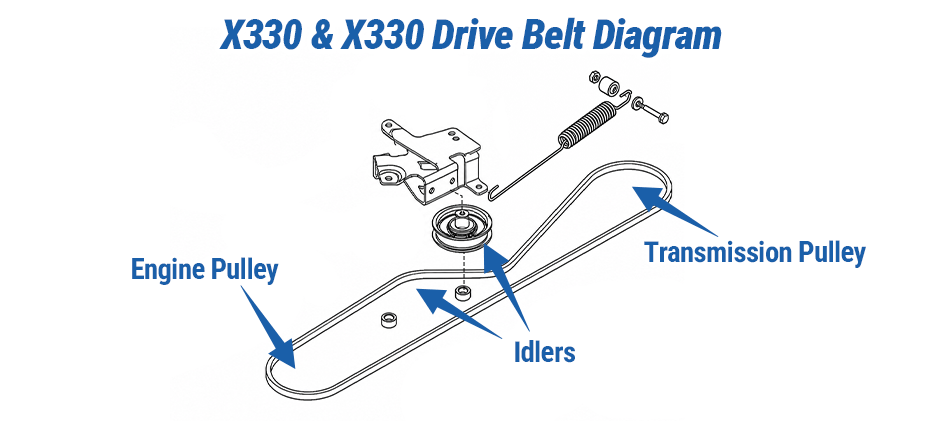
- Key Components: The system includes the drive belt, a large drive pulley, and a tensioner arm that holds two separate idler pulleys A tension spring provides the force.
- Routing Path: The belt travels from the engine pulley to the transmission pulley at the rear. The tensioner arm is strategically placed so that its two idlers press against the belt from opposite sides, creating a serpentine “S” shape. This dual-contact design provides excellent grip and stable tension, which is necessary for the capabilities of the X Series tractors. Various belt guides are also used to prevent the belt from derailing.
LX Series
The LX series tractors often included a variable-speed drive system, which makes the John Deere drive belt diagram a bit more complex than on other models.
John Deere LX176 Drive Belt Diagram
The diagram for the LX176 shows a system designed to handle variable pulley diameters.
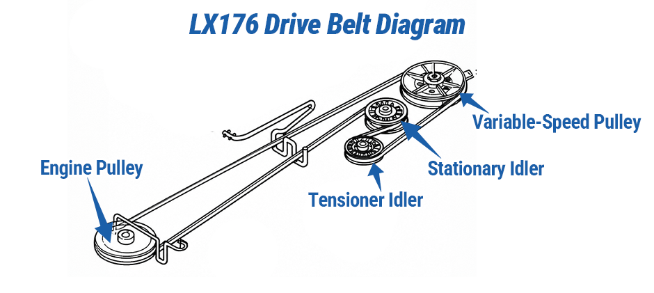
- Key Components: This system uses a primary drive belt, a tensioner idler, a spring, and a variable-speed pulley. A secondary belt (not numbered the same) goes from this variable pulley to the transmission pulley.
- Routing Path: We will focus on the primary drive belt. It runs from the engine pulley to the variable-speed pulley. The tensioner idler, pulled by a spring, presses against this belt to keep it tight as the variable pulley changes its effective diameter to adjust ground speed.
John Deere 345 Drive Belt Diagram
The John Deere 345 is a garden tractor known for its robust hydrostatic transmission. The drive belt system can handle the higher torque loads.
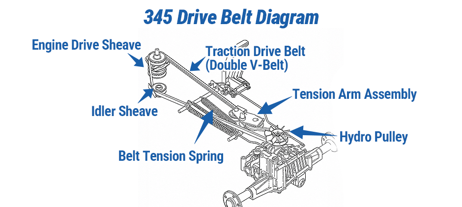
- Key Components: This model uses a heavy-duty Traction Drive Belt (Double V-Belt). Key parts include the engine drive sheave, an idler sheave, a tension arm assembly, a long belt tension spring, and the input sheave on the hydrostatic transmission.
- Routing Path: The double V-belt comes from the engine drive sheave at the front of the tractor. It wraps around a large idler sheave before heading back to the dual-groove pulley on top of the hydrostatic transmission. The tension arm assembly, equipped with its own idler, is pulled by the long tension spring. This arm presses against the belt span, ensuring there is no slippage under load.
How to Replace the Drive Belts?
Steps differ a little based on your mower model, but the basic process for replacing a transaxle drive belt stays the same. Warning: Drive belt assemblies have tight spring tension. Always put on safety goggles. Take extra care when loosening or resetting tension — you could hurt yourself.
Prepartion
- Park the mower safely: Set your mower on flat ground, pull the parking brake on, shut off the engine and take out the ignition key.
- Take off the mower deck: You’ll nearly always need to remove the deck to reach the drive belt. Check your owner’s manual for the proper way to detach it.
Specific Steps
- Loosen the belt tension: Find the spring tensioner arm. Use a long socket wrench, breaker bar on the tensioner bolt, or a metal stick in the lever hole to push the arm away from the belt. This lets the belt go slack.
- Pull off the old belt: With tension released, slide the old belt off the tension pulley first, then work it free from all other pulleys. If the belt hasn’t snapped yet, snap a picture of how it’s threaded before you fully take it off.
- Thread on the new belt: Loop the new drive belt around the engine pulley and transaxle pulley first. Make sure the V-shaped edge sits fully inside each pulley’s groove.
- Wind the belt around idle pulleys: Stick to the John Deere belt diagram matching your model. Thread the belt around all fixed idle pulleys and line it up next to the tensioner pulley.
- Reset the tension: Hold the belt steady, then slowly let the tensioner arm snap back so its pulley presses tight against the new belt. Double-check the belt fits fully into every pulley groove.
- Finish everything up: Plug back in any wiring you unplugged (like the electric clutch wire). Bolt the mower deck back on, and your mower’s good to use again.
Wrapping Up
Use the right diagram and follow the steps to replace the belt safely. When you need a new belt or other parts, check out FridayParts. And we offer compatible parts for many John Deere mowers and models, so you can get your mower back to work sooner.
