
Have you ever wondered how your wheeled machines’ and vehicles’ wheels turn at different speeds? The inside and outside wheels travel unequal distances in a turn, while still working together harmoniously without fighting each other and causing wear. The secret behind this is a delicate mechanical device: the differential. Whether you’re a driver to figure out or a technician repairing a differential in your workshop, this guide will help you deeply understand its function, working principles, and key components with a differential diagram.
What is a Differential with Diagram?
A differential is a gear mechanism in vehicles that lets the left and right drive wheels rotate at different speeds (e.g., when turning), while still sending power from the engine to the wheels.
Main Functions of a Differential
Changes the Direction of Power: The engine’s power travels down the length of the driveshaft. A set of gears on the differential turns that power 90 degrees to drive the wheels.
Alters Torque Through Gear Reduction: The gearing inside the differential provides a final gear reduction, slowing the rotational speed from the transmission one last time before it reaches the wheels. This process multiplies torque, giving your machine the twisting force it needs to move heavy loads.
Splits Power to the Wheels: It takes the single stream of power from the driveshaft and divides it between the two drive wheels on the axle.
Allows Wheels to Turn at Different Speeds: This feature is well known to the public. When turning, the outer wheel must travel a longer distance than the inner wheel. The differential allows the left and right wheels to rotate at different speeds when turning, achieving automatic adjustment.
How Does the Differential Work?
As you drive the vehicle in a straight line, the internal gears of the differential remain essentially stationary relative to each other. Both wheels have the same power, so they rotate at the same speed. However, once the turn begins, the situation changes. The inside wheels begin to slow down while traveling a shorter arc, while the outside wheels require acceleration to travel longer distances. The differential can sense this difference in drag. The small “spider gear” inside the differential rotates, passing more rpm to the outside wheels and less rpm to the inside wheels. This process ensures that the power is always smooth, prevents the wheels from beating, reduces tire wear, and minimizes the burden on the entire drivetrain.
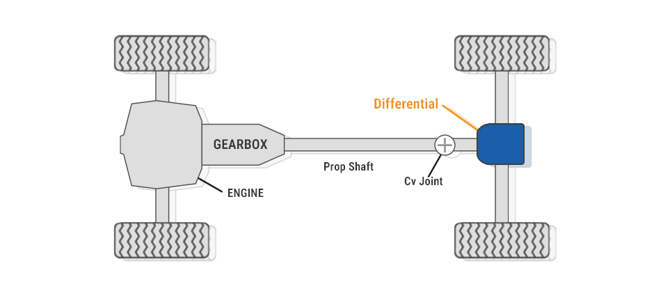
Where Is the Differential Located on a Machine with A Diagram?
You will find a differential on any powered axle. The exact location depends on the machine’s drive configuration: it may be located at the front of the machine along the front axle, at the rear of the machine along the rear axle, or at the center of the machine dividing the front axle and the rear axle.
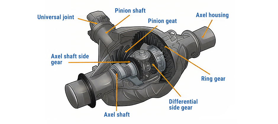
What are the Components of A Differential Diagram?
To truly understand how a differential works, we need to look at its key parts. Each component has a specific job, and they all work together in a finely tuned mechanical dance. This section is your guide to the anatomy of a typical differential with a Diagram.
Pinion Drive Gear
The Pinion Drive Gear is where the power first enters the differential. This small, beveled gear is connected to the end of the driveshaft. As the driveshaft spins, it turns the pinion gear. Its main job is to transfer the engine’s power to the much larger ring gear. The size difference between the pinion and ring gear is what creates the final gear reduction ratio.
Ring Gear
The Ring Gear is a large, circular gear that is bolted directly to the differential case. Its teeth mesh perfectly with the teeth of the pinion drive gear. When the pinion gear spins, it forces the ring gear to rotate, thereby turning the entire differential case assembly along with it. This interaction is what redirects the power 90 degrees from the driveshaft to the axles.
Side/Spider Gears
These are the “brains” of the operation. Inside the differential case, you’ll find a set of smaller gears. The two Side Gears are splined to the inner ends of the two axles. Between them are two or more Spider Gears (also known as pinion gears, not to be confused with the main drive pinion). When the machine is driving straight, these gears are locked together and turn as one unit. When turning, the spider gears walk around the side gears, allowing one axle to speed up and the other to slow down.
Differential Case Assembly
This is the housing that holds the ring gear, side gears, and spider gears. The ring gear is bolted to the outside of the case. As the ring gear rotates, it spins the entire case. The case’s job is to contain all the internal components and transfer the rotational force from the ring gear to the spider gears inside.
Axle Housing
The Axle Housing is the large, strong metal tube or casting that encloses the entire differential assembly and the drive axles. It protects these critical components from dirt, water, and damage. It also serves as a mounting point for the suspension and braking systems and is filled with gear oil to lubricate everything.
Rear Axle Bearings
Ball or roller bearings that fit between the axles and the inside of the axle housing. There are carrier bearings that support the differential case within the axle housing, and wheel bearings at the outer ends of the housing that support the weight of the machine and allow the wheels to rotate freely.
Rear Drive Axles
These are the steel shafts that ultimately deliver power to the wheels. The inner end of each axle has splines that connect to the side gears inside the differential. The outer end connects to the wheel hub. They are responsible for transferring the final torque from the differential assembly to the drive wheels.
Common Types of Differentials
Different types are designed for different applications, balancing the need for smooth turning with the need for maximum traction.
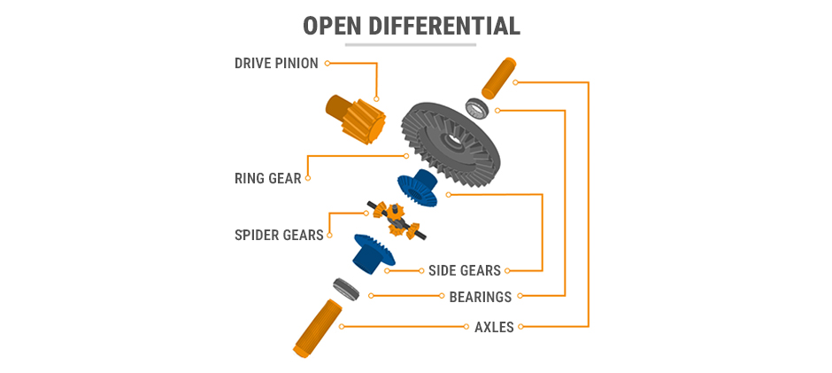
Open (or standard) differential
This is the most common and basic type of differential. It allows the wheels to turn at different speeds for smooth turns. However, on low-traction surfaces, such as mud or ice, it transfers all power to the slipping wheels. This means that one wheel will idle, while a wheel with good grip will not get the power. End up jamming the vehicle at the final.
Locked Differential
Locked Differential mechanically locks the two axles together, forcing both wheels to turn at the same speed, regardless of traction. This provides extreme traction on slippery surfaces, as both wheels always get 50% power. However, it is very difficult to turn on high-traction surfaces, causing severe tire wear and pressure on axle components.
Limited Slip differential (LSD)
Under normal conditions, it acts like an open differential for smooth steering. However, when one wheel is starting to slip, the clutch or gear system inside the LSD automatically engages, transmitting more power to the wheel with more traction. This gives you the advantages of both driving styles: smooth road handling and increased traction when needed.
Wrapping Up
The differential plays an important role in steering power, increasing torque, and achieving smooth turns. Component wear affects the performance and safety of the machine. As an after-sales parts supplier with 16 years of experience in this field, FridayParts is here to help you. We have a large inventory of OEM-quality, affordable differential parts and extensive compatibility with numerous heavy equipment brands, ensuring you can get the parts you need to get back to work quickly.